
![]()
Follow Me.跟我来 :
: 
I am going to give you a quick introductory lesson on how to import and work with a point cloud file. First of all you need to open a scene to which you want to import the point cloud.
Go to File > Import > Cloud and choose your point cloud, in my case the file “hood.xyz”

Make your perspective window full size, then using ALT+SHIFT do a “Look at” to fit everything in the scene into view. If you do not have the View Panel then you might be using the View Cube. In which case you should click the little house icon next to the cube.

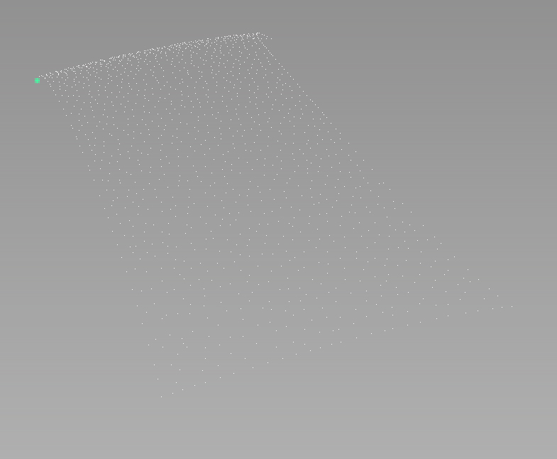
In order to better visualize the point cloud you can pick it using Pick > Cloud from the tools palette. Somehow clicking a point doesn’t work so well so I suggest you use a box select over a portion (or all) of the cloud, either method will select the entire cloud.

I am now seeing my point cloud (selected) as something like this
The first thing we’re going to want to do is turn it into a mesh, this can be done with the function Mesh > Cloud to Mesh from the tools pallete.

This function has a dialog box if you double-click the function in the tools palette after having selected your point cloud. I’m going to be frank that I think you are best off experimenting with the values and creating your mesh. And pick the one you find comes out as the best.

After a few different experimentation with the two tolerance settings, this is the mesh I chose to keep to continue with.

Now you can shade it if you like and delete the point cloud if you wish. I have done both here.

It is very important to consider the conversion from point cloud to mesh, is automatic. But the conversion from mesh to surface won’t be. The mesh is a rough guide and more often than not way to coarse be used as input for the Mesh to Surface command in Alias directly.
As a result I will create a Plane in the tools palette and start modeling over the mesh.

I have snapped the vertices of my Plane (here in Green) to the edges of the mesh by using the Move tool and CTRL+ALT which is the mesh snap hot key combination.

I increased the degree of the surface to 3 by 3 in the control panel and turned on the CV hull.


And at this point it’s just a matter of pushing and pulling the CVs to conform to the shape of the mesh. It seems like a very manual way of reverse engineering these kinds of scanned objects, and that’s because, it is. But if you want a model that has perfect highlights and a logical CV structure that can be easily edited and changed, there is currently no better way to it.
Take comfort in the fact that Alias provides some of the most intuitive and fastest CV pushing and pulling workflows in the industry. That is where the power comes from. Not a whole bunch of fancy algorithms and functions but instead, a down to earth philosophy that works. Streamlined by the commands and functions that Alias puts to the fore.
Roll your camera view obliquely against the grey background, look at the CV and hull lines and make sure they are clean with no single CV sticking out or dipping in abruptly.

Looking at the entire model it may look something a little like this.

You may also use the Deviation Map in the tools palette to give you a view of how close you are to the mesh, remember the mesh is our guide, not our Bible.

As you can see we still have some work to do, we’d like to get it anywhere between 1mm and 5mm. With our CVs pretty well aligned this seemingly coarse result we have right now (maybe about 30mm from the mesh) can be tuned very quickly with the deviation map. Whatever you do, do not put on the Deviation Map unless your CV layout it 90% there. Otherwise you will get very frustrated!

Now whatever you do, don’t start pulling CVs willy nilly. Do the same technique we used before, roll your camera view so that you see the CVs and hull lines against the horizon. Like such.

We’re going to use the Transform CV tool (the old Move CV tool for the Alias veterans) and then press the Spacebar to bring up this handy little pop up menu, choose the NUV mode to move CV’s normal to the surface.

Another important point to make is never to focus solely on the CV directly under the area of the coloured plot you wish to turn green, move it but also the CV to the right, front, forward and back of it. Think of it like a thin piece of metal you would bend in real life, it needs to be balanced. All of the CVs work together to define the surface. In fact that is the big defining characteristic of bézier curves and surfaces. There is very little local control. We like that. It means smooth curves, and smooth surfaces.
Here I am working with a group of 4 to 6 CVs at once making the colour turn green gradually across an ever increasing region of the mesh.

I don’t pull these all at once, one at a time. A little bit at a time.
There is nothing rocket sciencey about this, I wish there was. You know? But the truth of the matter is, that there ain’t. It just takes a lot of practice and patience. Patience above all I suppose. I wouldn’t go as far as say it tests your desire to live, haha, but it is a pretty laborious process doing reverse engineering! Even in the year 2013, and for the forseeable future to come.
As Uwe Rossbacher from Autodesk said: “it may get easier in the future, but for now this is what we have to work with.”
And it works though, it definitely works. Under the hands of an expert Alias user even the time it takes it surprisingly reduced. It’s pretty great, yes?
There’s nothing worse though than finding out your current patch layout and CV placement ain’t gonna cut it to get the model to the mesh to a close enough tolerance. Don’t force it, it ain’t gonna happen. Let it go. Re-think your patch layout. It sucks. Move on 🙂
As you can see this is looking a lot better after just 10 minutes of work.

There are other validation methods too, such as shining iso-lines across our surface. Remember the mesh is not the Bible, unless they told you it was the Bible. Then it is the Bible 🙂
I have hid my mesh so only my surface is visible and then double-clicked on the Iso Angle tool in the tools palette. Also known as “the best surface analysis tool in Alias” according to some users.

Now. Unlike most of Alias, this tool is kind of like rocket science. Heh! I have found in my experience you need to use the visual curves option, forget about the colours. If you want to use them though, please do feel free to.

Because this is what we see with the default settings. Hmm. Yes our surface is the awesome! No wait. We’re not seeing anything right now apart from a pale white spot. Let’s change that. First off change the settings so that we see this resultant.

Now we just see a bunch of rings though. If have found the best results are gathered when making the light shine obliquely across the surface (obliquely is like the key in Alias, remember the CV and hull viewing them obliquely helped best?)

One may want to move the CVs using NUV ever so slightly, to attain a result closer to something like this. (note I changed the number of bands to 40 and made the tolerance value coarser for faster real time updating of the iso angle visual curves)

What you can also do is cut curvature combs through your surface. Use the tool Curvature in the bottom of your modeling palette.

Simply turn on the Curvature U (or V) in the display section, and under the Curvature setting just enter how many cuts your want and how big the scale should be and sampling rate. Something like to become what you see below.

And now the other direction, I recommend looking at one direction at a time.

I hope this helped you out!
“Advanced LA student
Kevin De Smet”